| Image Processing Toolbox User's Guide | |
Working with Fan-Beam Projection Data
The commands below illustrate how to use fanbeam and ifanbeam to form projections from a sample image and then reconstruct the image from the projections. The test image is the Shepp-Logan head phantom, which can be generated by the Image Processing Toolbox function phantom. The phantom image illustrates many of the qualities that are found in real-world tomographic imaging of human heads.
FanSensorSpacing parameter to vary the sensor spacing. The example uses the fanbeam arc geometry, so you specify the spacing between sensors by specifying the angular spacing of the beams. The first call spaces the beams at 2 degrees; the second at 1 degree; and the third at 0.25 degrees. In each call, the distance between the center of rotation and vertex of the projections is constant at 250 pixels. In addition, fanbeam rotates the projection around the center pixel at 1 degree increments.
D = 250;

dsensor1 = 2;
F1 = fanbeam(P,D,'FanSensorSpacing',dsensor1);

dsensor2 = 1;
F2 = fanbeam(P,D,'FanSensorSpacing',dsensor2);

dsensor3 = 0.25
[F3, sensor_pos3, fan_rot_angles3] = fanbeam(P,D,...
'FanSensorSpacing',dsensor3);
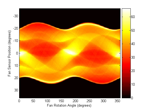
F3. Because fanbeam calculates projection data at rotation angles from 0 to 360 degrees, the same patterns occur at an offset of 180 degrees. The same features are being sampled from both sides. Compare this plot to the plot of the parallel-beam projection data of the head phantom on page 8-33.
figure, imagesc(fan_rot_angles3, sensor_pos3, F3)
colormap(hot); colorbar
xlabel('Fan Rotation Angle (degrees)')
ylabel('Fan Sensor Position (degrees)')
ifanbeam. In each reconstruction, match the fan sensor spacing with the spacing used when the projection data was created in step 2. The example uses the OutputSize parameter to constrain the output size of each reconstruction to be the same as the size of the original image |P|.
output_size = max(size(P));

Ifan1 = ifanbeam(F1,D,
       'FanSensorSpacing',dsensor1,'OutputSize',output_size);
figure, imshow(Ifan1)

Ifan2 = ifanbeam(F2,D,
       'FanSensorSpacing',dsensor2,'OutputSize',output_size);
figure, imshow(Ifan2)

Ifan3 = ifanbeam(F3,D,
       'FanSensorSpacing',dsensor3,'OutputSize',output_size);
figure, imshow(Ifan3)
Ifan1, was created using 2 degree spacing of the beams; the second image, ifan2, was created using 1 degree spacing of the beams; the third image, ifan3, was created using 0.25 spacing of the beams.
Reconstructions of the Head Phantom Image from Fan-Beam Projections
| | Reconstructing an Image from Fan-Beam Projection Data | Morphological Operations | |
© 1994-2005 The MathWorks, Inc.