| Neural Network Toolbox | |
Using the NN Predictive Controller Block
This section demonstrates how the NN Predictive Controller block is used.The first step is to copy the NN Predictive Controller block from the Neural Network Toolbox blockset to your model window. See your Simulink documentation if you are not sure how to do this. This step is skipped in the following demonstration.
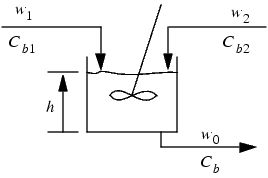
A demo model is provided with the Neural Network Toolbox to demonstrate the predictive controller. This demo uses a catalytic Continuous Stirred Tank Reactor (CSTR). A diagram of the process is shown in the following figure.
The dynamic model of the system is
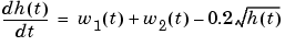
where  is the liquid level,
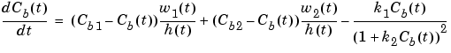
  is the product concentration at the output of the process,
  is the flow rate of the concentrated feed
  , and
, and  is the flow rate of the diluted feed
  . The input concentrations are set to
  and
and  . The constants associated with the rate of consumption are
  and
and  .
.
The objective of the controller is to maintain the product concentration by adjusting the flow  . To simplify the demonstration, we set
  . The level of the tank
  is not controlled for this experiment.
To run this demo, follow these steps.
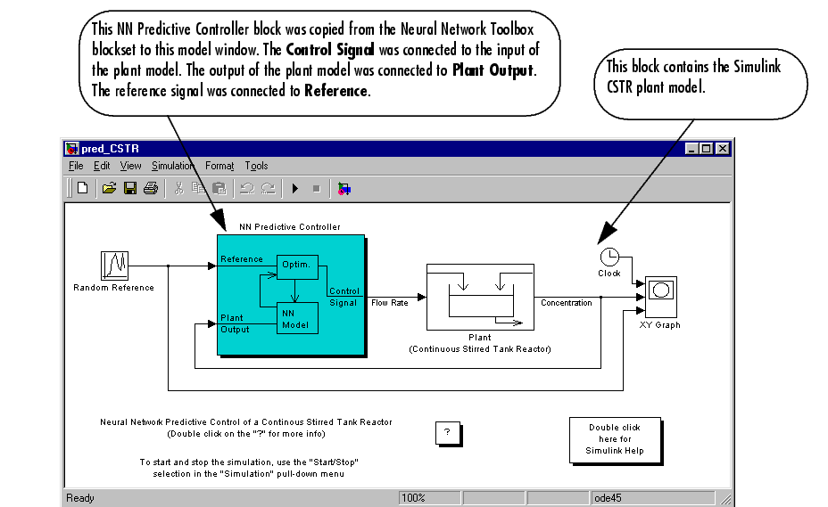
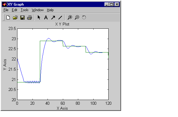
predcstr in the MATLAB command window. This command starts Simulink and creates the following model window. The NN Predictive Controller block has already been placed in the model.
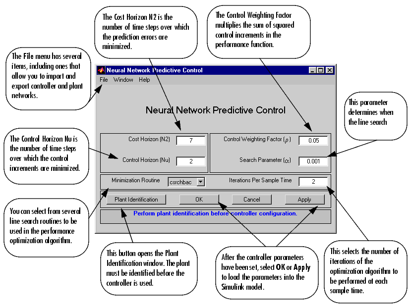
 and
and  . (
. ( is fixed at 1.) The weighting parameter
  , described earlier, is also defined in this window. The parameter
  is used to control the optimization. It determines how much reduction in performance is required for a successful optimization step. You can select which linear minimization routine is used by the optimization algorithm, and you can decide how many iterations of the optimization algorithm are performed at each sample time. The linear minimization routines are slight modifications of those discussed in Backpropagation.
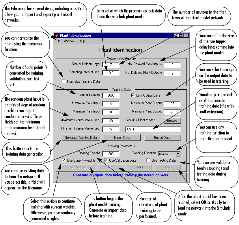
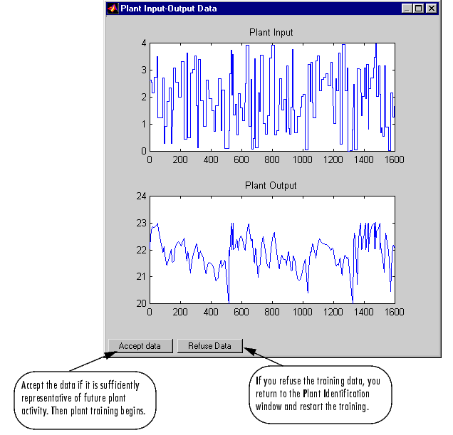
trainlm in this case). This is a straightforward application of batch training, as described in Backpropagation. After the training is complete, the response of the resulting plant model is displayed, as in the following figure. (There are also separate plots for validation and testing data, if they exist.) You can then continue training with the same data set by selecting Train Network again, you can Erase Generated Data and generate a new data set, or you can accept the current plant model and begin simulating the closed loop system. For this demonstration, begin the simulation, as shown in the following steps.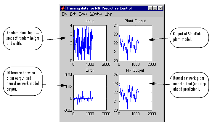
| | Predictive Control | NARMA-L2 (Feedback Linearization) Control | |
© 1994-2005 The MathWorks, Inc.