| Signal Processing Toolbox |
  |
Exporting to Simulink
If you have Simulink installed, you can export a Simulink block of your filter design and insert it into a new or existing Simulink model.
You can export a filter designed using any filter design method available in FDATool.
| Note
If you have the Filter Design Toolbox, you can export a CIC filter to Simulink, if you also have these toolboxes and blocksets installed in addition to Simulink: the Fixed-Point Toolbox and the Signal Processing Blockset.
|
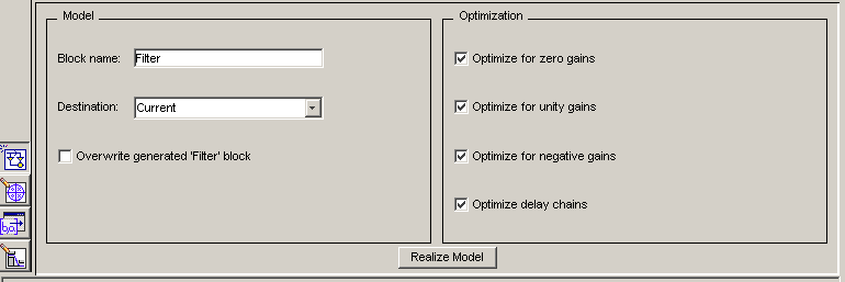
- After designing your filter, click the Realize Model sidebar button or select Export to Simulink Model from the File menu. The Realize Model panel is displayed.

- Specify the name to use for your block in Block name.
- Select the Destination --
Current to insert the block into the current (most recently selected) Simulink model or New to open a new model.
- If you want to overwrite a block previously created from this panel, check Overwrite generated `Filter' block.
| Note
If you have the Signal Processing Blockset installed, a Build model using basic elements check box is included. If you deselect it, a Digital Filter block is created instead of a subsystem block, which uses separate subelements. See the Filter Realization Wizard and Choosing Between Filter Design Blocks in the Signal Processing Blockset documentation for information.
|
- Select the desired optimization(s) for your block:
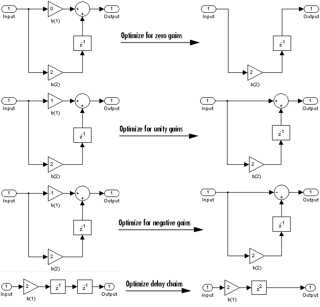
- Optimize for zero gains -- removes zero-valued gain paths from the filter structure.
- Optimize for unity gains -- substitutes a wire (short circuit) for gains equal to 1 in the filter structure.
- Optimize for negative gains -- substitutes a wire (short circuit) for gains equal to -1 and changes corresponding additions to substractions in the filter structure.
- Optimize delay chains -- substitutes delay chains composed of
n unit delays with a single delay of n.
The following illustration shows the effects of each optimization:

- Click the Realize Model button to create the filter block. The filter is implemented as a subsytem block using Sum, Gain, and Integer Delay blocks.

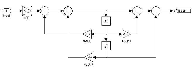
If you double-click the Filter block in Simulink, the filter structure is displayed. The following figure shows the first section of the default four-section, direct form II filter.

 | Exporting to SPTool | | Generating a C Header File |  |
© 1994-2005 The MathWorks, Inc.


