| 3-D Visualization | |
Example -- Moving the Camera Through a Scene
A fly-through is an effect created by moving the camera through three-dimensional space, giving the impression that you are flying along with the camera as if in an aircraft. You can fly through regions of a scene that might be otherwise obscured by objects in the scene or you can fly by a scene by keeping the camera focused on a particular point.
To accomplish these effects you move the camera along a particular path, the x-axis for example, in a series of steps. To produce a fly-through, move both the camera position and the camera target at the same time.
The following example makes use of the fly-though effect to view the interior of an isosurface drawn within a volume defined by a vector field of wind velocities. This data represents air currents over North America.
See coneplot for a fixed visualization of the same data.
Summary of Techniques
This example employs a number of visualization techniques. It uses
Graphing the Volume Data
The first step is to draw the isosurface and plot the air flow using cone plots.
See isosurface, isonormals, reducepatch, and coneplot for information on using these commands.
Setting the data aspect ratio (daspect) to [1,1,1] before drawing the cone plot enables MATLAB to calculate the size of the cones correctly for the final view.
load wind
wind_speed = sqrt(u.^2 + v.^2 + w.^2);

hpatch = patch(isosurface(x,y,z,wind_speed,35));
isonormals(x,y,z,wind_speed,hpatch)
set(hpatch,'FaceColor','red','EdgeColor','none');

[f vt] = reducepatch(isosurface(x,y,z,wind_speed,45),0.05);
daspect([1,1,1]);
hcone = coneplot(x,y,z,u,v,w,vt(:,1),vt(:,2),vt(:,3),2);
set(hcone,'FaceColor','blue','EdgeColor','none');
Setting Up the View
You need to define viewing parameters to ensure the scene is displayed correctly:
camproj).
camva).
Specifying the Light Source
Positioning the light source at the camera location and modifying the reflectance characteristics of the isosurface and cones enhances the realism of the scene:
camlight).
AmbientStrength set to 0.1) with highly reflective material (SpecularStrength and DiffuseStrength set to 1).
SpecularStrength of the cones to 1 makes them highly reflective.
Selecting a Renderer
Because this example uses lighting, MATLAB must use either zbuffer or, if available, OpenGL renderer settings. The OpenGL renderer is likely to be much faster displaying the animation; however, you need to use gouraud lighting with OpenGL, which is not as smooth as phong lighting, which you can use with the zbuffer renderer. The two choices are
Defining the Camera Path as a Stream Line
Stream lines indicate the direction of flow in the vector field. This example uses the x-, y-, and z-coordinate data of a single stream line to map a path through the volume. The camera is then moved along this path. The tasks include
stream3 to calculate the stream line data without actually drawing the stream line).
Implementing the Fly-Through
To create a fly-through, move the camera position and camera target along the same path. In this example, the camera target is placed five elements further along the x-axis than the camera. A small value is added to the camera target x position to prevent the position of the camera and target from becoming the same point if the condition xd(n) = xd(n+5) should occur:
drawnow to display the results of each move.
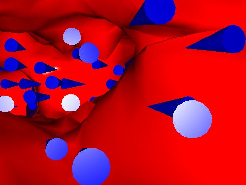
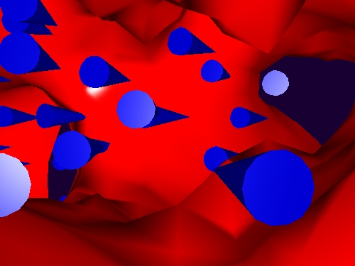
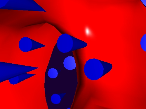
These snapshots illustrate the view at values of i equal to 10, 110, and 185.
| | Example -- Dollying the Camera | Low-Level Camera Properties | |
© 1994-2005 The MathWorks, Inc.