
| Signal Processing Toolbox |   |
Frequency Transformation
The second step in the analog prototyping design technique is the frequency transformation of a lowpass prototype. The toolbox provides a set of functions to transform analog lowpass prototypes (with cutoff frequency of 1 rad/s) into bandpass, highpass, bandstop, and lowpass filters of the desired cutoff frequency.
| Freq. Transformation |
Transformation Function |
Lowpass to lowpass |
[numt,dent][At,Bt,Ct,Dt] |
Lowpass to highpass |
[numt,dent][At,Bt,Ct,Dt] |
Lowpass to bandpass |
[numt,dent][At,Bt,Ct,Dt] |
Lowpass to bandstop |
[numt,dent][At,Bt,Ct,Dt] |
As shown, all of the frequency transformation functions can accept two linear system models: transfer function and state-space form. For the bandpass and bandstop cases


where  1 is the lower band edge and
  2 is the upper band edge.
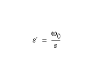
The frequency transformation functions perform frequency variable substitution. In the case of lp2bp and lp2bs, this is a second-order substitution, so the output filter is twice the order of the input. For lp2lp and lp2hp, the output filter is the same order as the input.
To begin designing an order 10 bandpass Chebyshev Type I filter with a value of 3 dB for passband ripple, enter
Outputs z, p, and k contain the zeros, poles, and gain of a lowpass analog filter with cutoff frequency  c equal to 1 rad/s. Use the
 lp2bp function to transform this lowpass prototype to a bandpass analog filter with band edges  and
and  . First, convert the filter to state-space form so the
 lp2bp function can accept it:
Now, find the bandwidth and center frequency, and call lp2bp:
u1 = 0.1*2*pi;  u2 = 0.5*2*pi; % In radians per second
Bw = u2-u1;
Wo = sqrt(u1*u2);
[At,Bt,Ct,Dt] = lp2bp(A,B,C,D,Wo,Bw);
Finally, calculate the frequency response and plot its magnitude:
[b,a] = ss2tf(At,Bt,Ct,Dt);       % Convert to TF form.
w = linspace(0.01,1,500)*2*pi;    % Generate frequency vector.
h = freqs(b,a,w);                 % Compute frequency response.
semilogy(w/2/pi,abs(h)), grid     % Plot log magnitude vs. freq.
xlabel('Frequency (Hz)');
 | Analog Prototype Design | Filter Discretization |  |
© 1994-2005 The MathWorks, Inc.