| Signal Processing Toolbox | |
Syntax
Description
fvtool(b,a)
opens FVTool and computes the magnitude response of the digital filter defined with numerator, b and denominator, a. Using FVTool you can display the phase response, group delay, impulse response, step response, pole-zero plot, and coefficients of the filter. You can export the displayed response to a file with Export on the File menu.
fvtool(b1,a1,b2,a2,...bn,an)
opens FVTool and computes the magnitude responses of multiple filters defined with numerators, b1...bn and denominators, a1...an.
fvtool(Hd1,Hd2,...)
opens FVTool and computes the magnitude responses of the filters in the dfilt objects Hd1, Hd2, etc. If you have the Filter Design Toolbox installed, you can also use fvtool(H1,H2,...) to analyze quantized filter objects (dfilt with arithmetic set to 'single'), multirate filter (mfilt) objects, and adaptive filter (adaptfilt) objects.
h = fvtool(...)
returns a figure handle h. You can use this handle to interact with FVTool from the command line. See Controlling FVTool from the MATLAB Command Line below.
| Icon |
Description |
 |
Toggle legend |
 |
Toggle grid |
 |
Link to FDATool (appears only if started from FDATool) |
  |
Toggle Add mode/Replace mode (appears only if launched from FDATool) |
 |
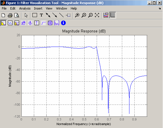
Magnitude response of the current filter. See To see the zero-phase response, right-click on the y-axis label of the Magnitude plot and select Zero-phase from the context menu. |
 |
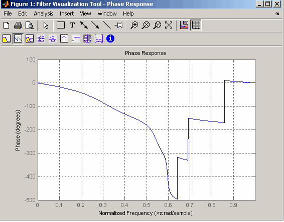
Phase response of the current filter. See phasez for more information. |
 |
Superimposes the magnitude response and the phase response of the current filter. See |
 |
Shows the group delay of the current filter. Group delay is the average delay of the filter as a function of frequency. See grpdelay for more information. |
 |
Shows the phase delay of the current filter. Phase delay is the time delay the filter imposes on each component of the input signal. See phasedelay for more information |
 |
Impluse response of the current filter. The impulse response is the response of the filter to a impulse input. See impz for more information. |
 |
Step response of the current filter. The step response is the response of the filter to a step input. See stepz for more information. |
 |
Pole-zero plot, which shows the pole and zero locations of the current filter on the z-plane. See zplane for more information. |
 |
Filter coefficients of the current filter, which depend on the filter structure (e.g., direct-form, lattice, etc.) in a text box. For SOS filters, each section is displayed as a separate filter. |
 |
Detailed filter information. |
Linking to FDATool
In fdatool, selecting Filter Visualization Tool from the View menu or the Full View Analysis toolbar button
 when an analysis is displayed starts FVTool for the current filter. You can synchronize FDATool and FVTool with the FDAToolLink toolbar button
  . Any changes made to the filter in FDATool are immediately reflected in FVTool.
Two FDATool link modes are provided via the Set Link Mode toolbar button:
 --removes the filter currently displayed in FVTool and inserts the new filter.
 --retains the filter currently displayed in FVTool and adds the new filter to the display.
Modifying the Axes
You can change the x- or y-axis units by right-clicking the mouse on the axis label or by right-clicking on the plot and selecting Analysis Parameters. Available options for the axes units are as follows.
Modifying the Plot
You can use any of the plot editing toolbar buttons to change the properties of your plot.
Analysis Parameters are parameters that apply to the displayed analyses. To display them, right-click in the plot area and select Analysis Parameters from the menu. (Note that you can access the menu only if the Edit Plot button is inactive.) The following analysis parameters are displayed. (If more than one response is displayed, parameters applicable to each plot are displayed.) Not all of these analysis fields are displayed for all types of plots:
Linear or Log)
Specify freq. vector
Specify freq. vector is selected in Frequency Range.
Magnitude, Magnitude (dB), Magnitude squared, or Zero-Phase)
Magnitude (dB), the axes are always autoscaled. If unchecked, you can specify the y-axis (dB Display Range) as two values separated by a space.
Degrees or Radians)
Phase or Continuous Phase)
Samples or Time)
Default or Specified)
In addition to the above analysis parameters, you can change the plot type for Impulse and Step Response plots by right-clicking and selecting Line with Marker, Stem or Line from the context menu. You can change the x-axis units by right-clicking on the x-axis label and selecting Samples or Time.
To save the displayed parameters as the default values to use when FDATool or FVTool is opened, click Save as default.
To restore the MATLAB-defined default values, click Restore original defaults.
Data Markers display information about a particular point in the plot. See Using Data Markers for more information.
When FVTool is started from FDATool, you can use Design Masks to display filter specifications on a Magnitude plot. You can also draw your own spectral masks. See Analyzing the Filter for more information.
Overlaying a Response
You can overlay a second response on the plot by selecting Overlay Analysis from the Analysis menu and selecting an available response. A second y-axis is added to the right side of the response plot. The Analysis Parameters dialog box shows parameters for the x-axis and both y-axes.
Controlling FVTool from the MATLAB Command Line
After you obtain the handle for FVTool, you can control some aspects of FVTool from the command line. In addition to the standard Handle Graphics® properties (see Handle Graphics in the MATLAB documentation), FVTool has the following properties:
'Filters' -- returns a cell array of the filters in FVTool.
'Analysis' -- displays the specified type of analysis plot. The following table lists the analyses and corresponding analysis strings. 'Grid' -- controls whether the grid is 'on' or 'off'
'Legend' -- controls whether the legend is 'on' or 'off'
'Fs' -- controls the sampling frequency of filters in FVTool. The sampling frequency vector must be of the same length as the number of filters or a scalar value. If it is a vector, each value is applied to its corresponding filter. If it is a scalar, the same value is applied to all filters.
SosViewSettings -- (This option is available only if you have the Filter Deisgn Toolbox.) For second-order sections filters, this controls how the filter is displayed. The SOSViewSettings property contains an object so you must use this syntax to set it: set(h.SOSViewSettings,'View',viewtype), where viewtype is one of the following:
You can also define whether to use SecondaryScaling, which determines where the sections should be split. The secondary scaling points are the scaling locations between the recursive and the nonrecursive parts of the section. The default value is false, which does not use secondary scaling. To turn on secondary scaling, use this syntax: set(h.SOSViewSettings,'View','Cumulative',true)
{1:4} plots the combined response for all four sections, and entering {1,2,3,4} plots the response for each section individually.
Note
You can change other properties of FVTool from the command line using the set function. Use get(h) to view property tags and current property settings.
|
You can use the following methods with the FVTool handle.
addfilter(h,filtobj)
adds a new filter to FVTool. The new filter, filtobj, must be a dfilt filter object. You can specify the sampling frequency of the new filter with addfilter(h,filtobj,'Fs',10)
setfilter(h,filtobj)
replaces the filter in FVTool with the filter specified in filtobj. You can set the sampling frequency as described above.
deletefilter(h, index)
deletes the filter at the FVTool cell array index location.
legend(h,str1,str2,...)
str1 with filter 1, str2 with filter 2, etc. See legend in the MATLAB documentation for information.
For more information on using FVTool from the command line, see the demo fvtooldemo.
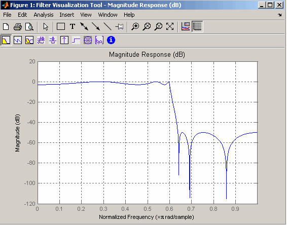
Example 1
Display the magnitude response of an elliptic filter, starting FVTool from the command line:
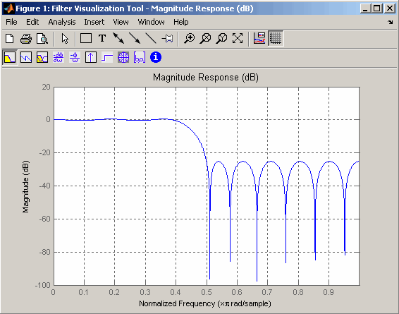
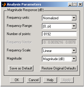
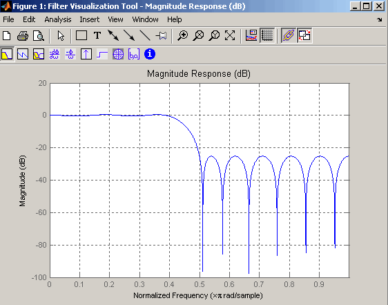
Example 2
Display and analyze multiple FIR filters, starting FVTool from the command line. Then, display the associated analysis parameters for the magnitude:
Right-click on the plot and select Analysis Parameters..
The displayed analysis parameters are normalized frequency units, frequency range zero (exclusive) to pi (inclusive), 8192 number of points, a display-only frequency vector, linear frequency scale, and magnitude in magnitude dB.
Example 3
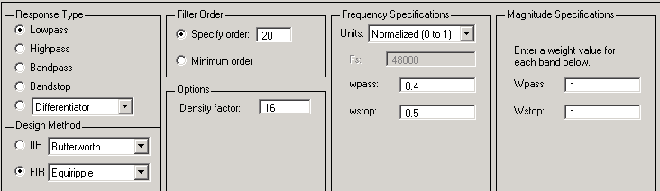
Create a lowpass, equiripple filter of order 20 in FDATool and display it in FVTool.
Set these parameters in fdatool:
and then click the Design Filter button.
Click the Full View Analysis button to start FVTool.
Example 4
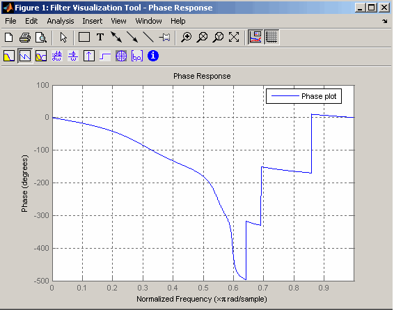
Create an elliptic filter and use some of FVTool's figure handle commands:
[b,a]=ellip(6,3,50,300/500); h = fvtool(b,a); % Create handle, h and start FVTool % with magnitude plot set(h,'Analysis','phase')% Change display to phase plot set(h,'Legend','on')% Turn legend on legend(h,'Phase plot')% Add legend text get(h)% View all properties% FVTool-specific properties are% at the end of this list. AlphaMap: [1x64 double] BackingStore: 'on' CloseRequestFcn: 'closereq' Color: [0.8314 0.8157 0.7843] ColorMap: [64x3 double] CurrentAxes: 208.0084 CurrentCharacter: '' CurrentObject: [] CurrentPoint: [0 0] DockControls: 'on' DoubleBuffer: 'on' FileName: '' FixedColors: [11x3 double] IntegerHandle: 'on' InvertHardcopy: 'on' KeyPressFcn: '' MenuBar: 'none' MinColormap: 64 Name: 'Filter Visualization Tool - Phase Response' NextPlot: 'new' NumberTitle: 'on' PaperUnits: 'inches' PaperOrientation: 'portrait' PaperPosition: [0.2500 2.5000 8 6] PaperPositionMode: 'manual' PaperSize: [8.5000 11] PaperType: 'usletter' Pointer: 'arrow' PointerShapeCData: [16x16 double] PointerShapeHotSpot: [1 1] Position: [360 292 560 345] Renderer: 'painters' RendererMode: 'auto' Resize: 'on' ResizeFcn: '' SelectionType: 'normal' ShareColors: 'on' Toolbar: 'auto' Units: 'pixels' WindowButtonDownFcn: '' WindowButtonMotionFcn: '' WindowButtonUpFcn: '' WindowStyle: 'normal' BeingDeleted: 'off' ButtonDownFcn: '' Children: [15x1 double] Clipping: 'on' CreateFcn: '' DeleteFcn: '' BusyAction: 'queue' HandleVisibility: 'on' HitTest: 'on' Interruptible: 'on' Parent: 0 Selected: 'off' SelectionHighlight: 'on' Tag: 'filtervisualizationtool' UIContextMenu: [] UserData: [] Visible: 'on' AnalysisToolbar: 'on' FigureToolbar: 'on' Filters: {[1x1 dfilt.df2t]} Grid: 'on' Legend: 'on' DesignMask: 'off' Fs: 1 SOSViewSettings: [1x1 dspopts.sosview] Analysis: 'phase' OverlayedAnalysis: '' ShowReference: 'on' PolyphaseView: 'off' NormalizedFrequency: 'on' FrequencyScale: 'Linear' FrequencyRange: '[0, pi)' NumberofPoints: 8192 FrequencyVector: [1x256 double] PhaseUnits: 'Radians' PhaseDisplay: 'Phase'
See Also
| | freqz | gauspuls | |
© 1994-2005 The MathWorks, Inc.